car-blink-hack
Car Hacking: How to Hack Hazard Lights with Arduino and an MCP2515
Introduction
In this post, I will explain how I used an Arduino Uno R3 and an MCP2515 CAN bus module to hack a 2012 Volkswagen Polo, inject messages onto its CAN bus, and control the hazard lights.
To fully understand this post, a basic understanding of what the CAN bus is and how it works is recommended. This video provides an excellent introduction to the fundamentals of the CAN serial communication protocol: Introduction to CAN Bus.
This article will not deeply explain the electrical principles or the low-level protocol of the CAN bus. Instead, it will focus on demonstrating how to access the CAN bus in a real vehicle and inject data onto it.
Disclaimer: This project was performed on a 2012 VW Polo. The process will likely be different for other vehicles, although the core principles may be similar. Always proceed with caution.
Tools and Dependencies
- Arduino Firmware: The Arduino firmware relies on the arduino-mcp2515 library to communicate with the MCP2515 module.
- Host Scripts: Since I use a MacBook, I could not use the standard
can-utilssuite, which is exclusive to Linux. To avoid using a VM, I created my own Python-based “copy” of some essentialcan-utilstools using thepython-canlibrary. All the scripts used in this guide can be found in my repository: can-utils-macos. But, if you can use can-utils library, the proccess will be basically the same.
Documentation
To make our lives easier, some documents provide highly relevant information about the CAN buses in vehicles: the Repair Manual and the Wiring Diagram. These documents aren’t perfect and won’t explicitly tell you how to hack your car, but they contain valuable information about the electrical system and its modules.
For this project, I found the Wiring Diagram, which mentioned three critical pieces of information:
- Powertrain CAN (Engine) and Comfort CAN (windows, doors, lights…).
- The COMFORT CAN bus bitrate is 500kbps.
- The
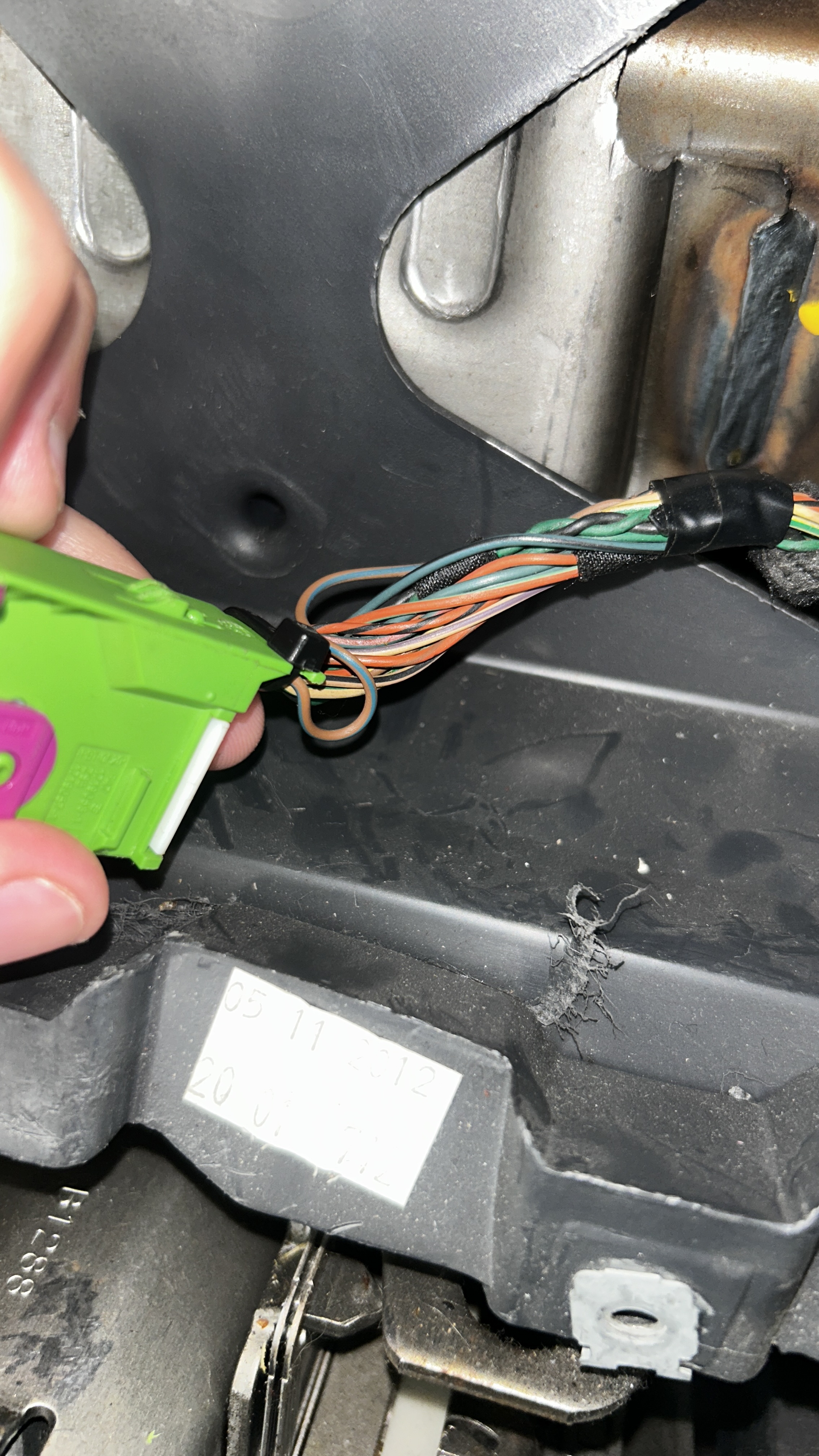
a-can-h(CAN High) anda-can-l(CAN Low) wires have the following colors: orange/black and orange/brown, respectively.
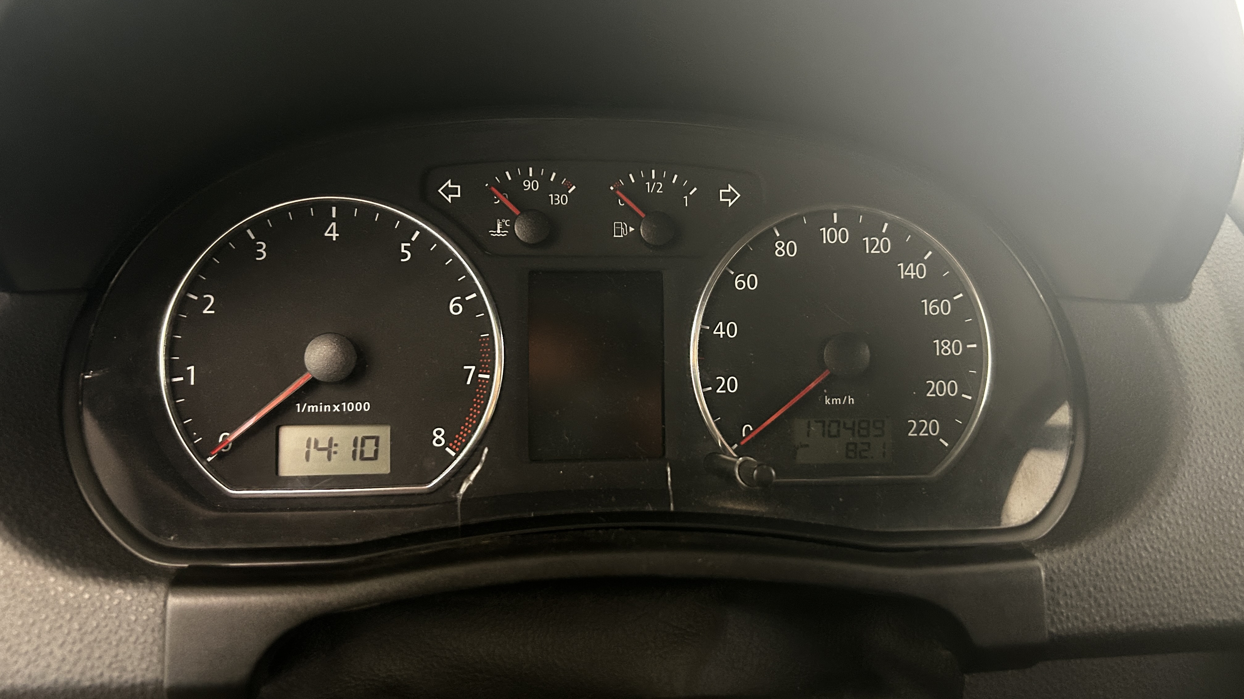
With this information, the next step is to find a physical location in the car that contains these wires. The documentation indicated that these wires are present in the instrument cluster (dashboard panel).
Finding the CAN Bus
Following the documentation, I removed the instrument cluster to verify the presence of the specified wires.
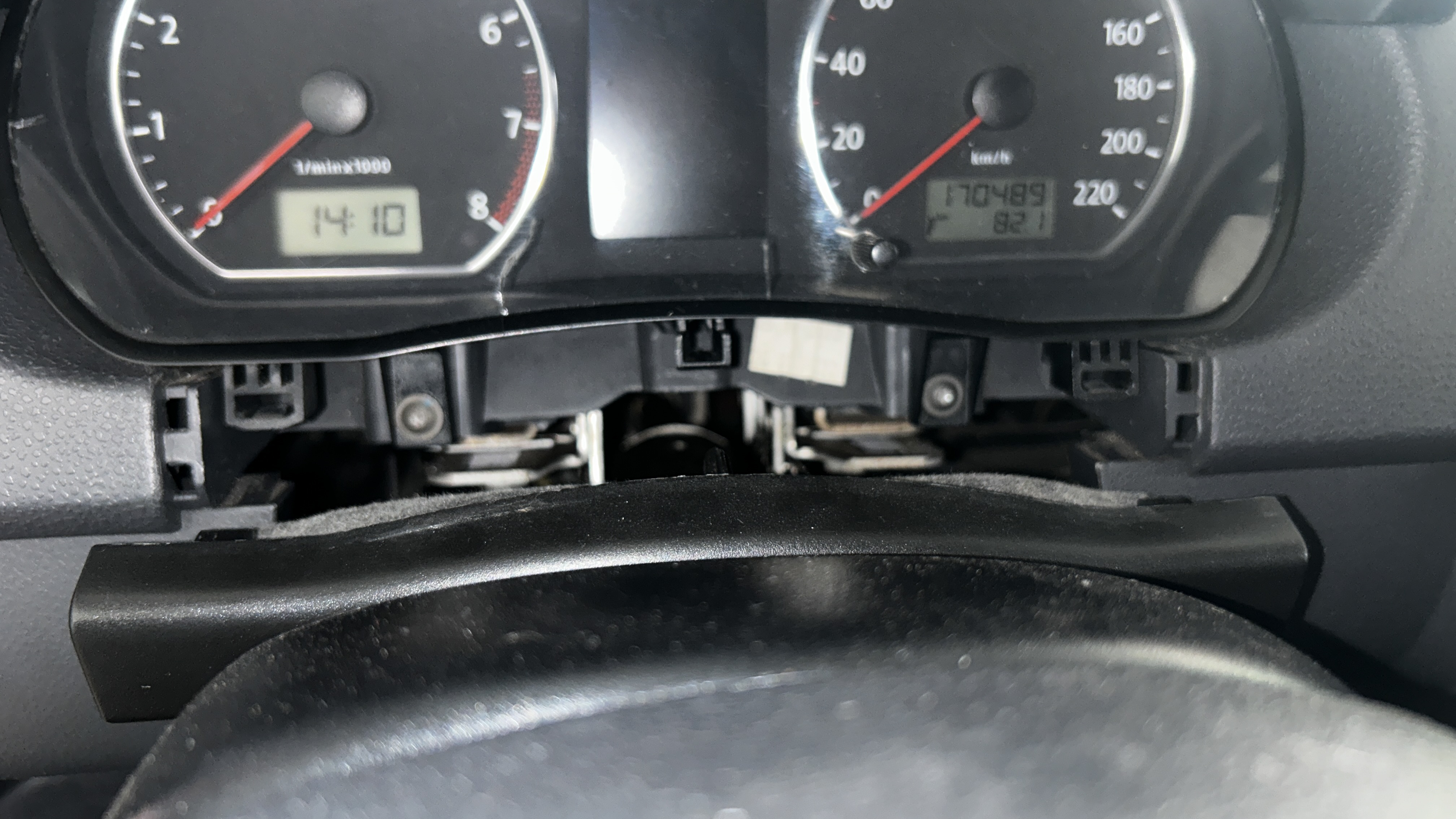
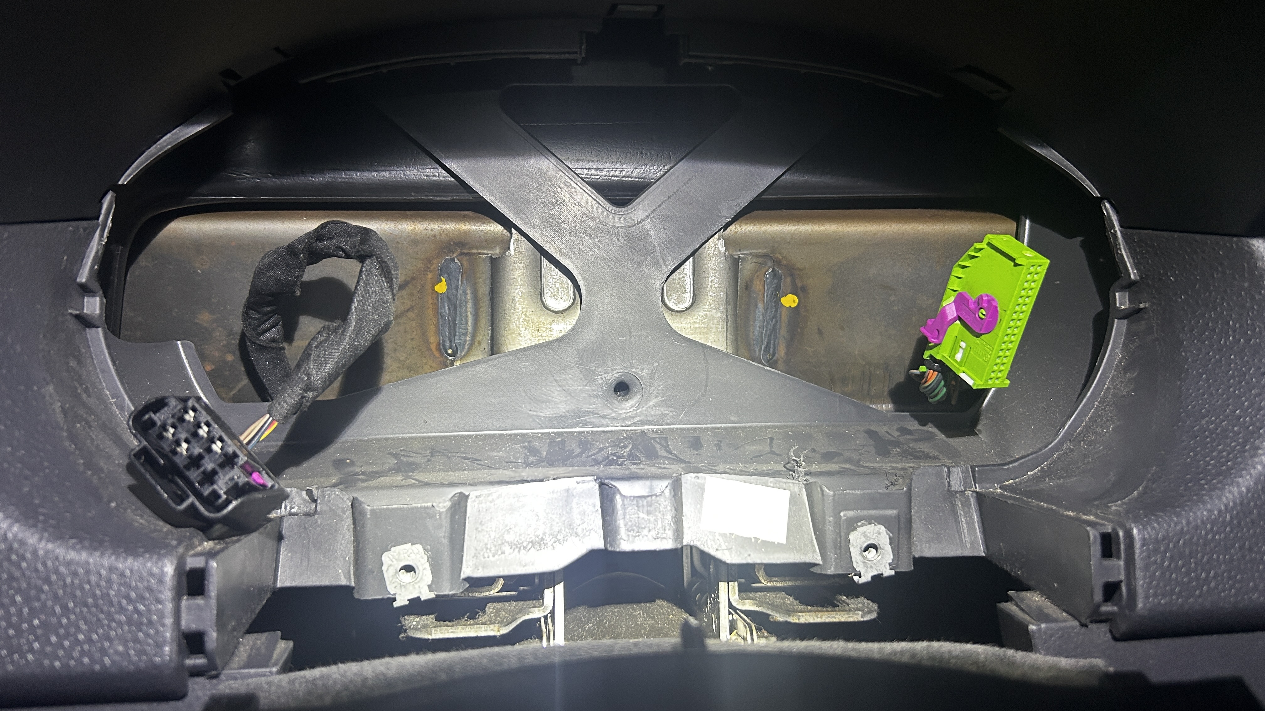
After removing the panel, I identified two main connectors. I located the target CAN wires in the green connector.
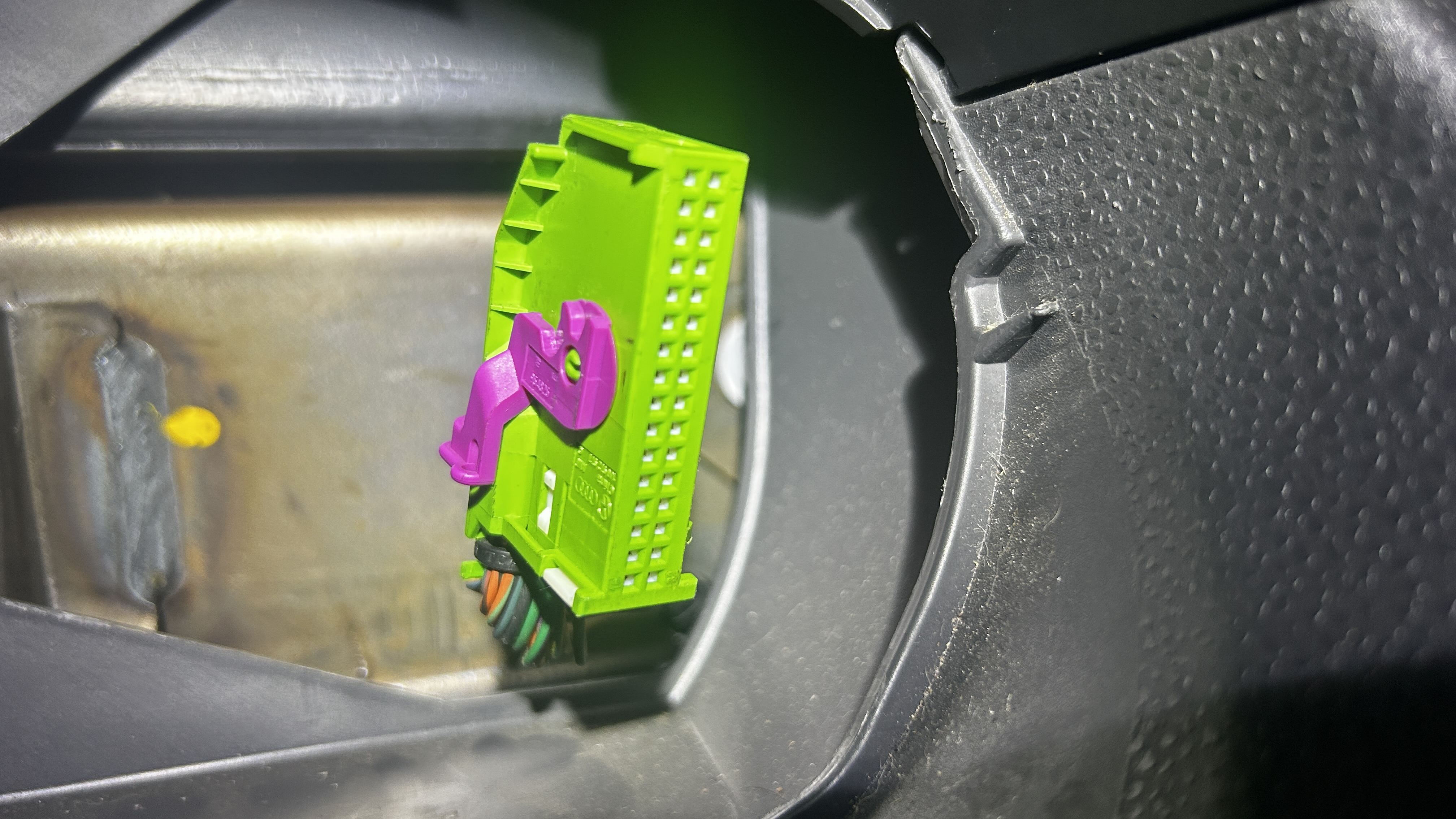
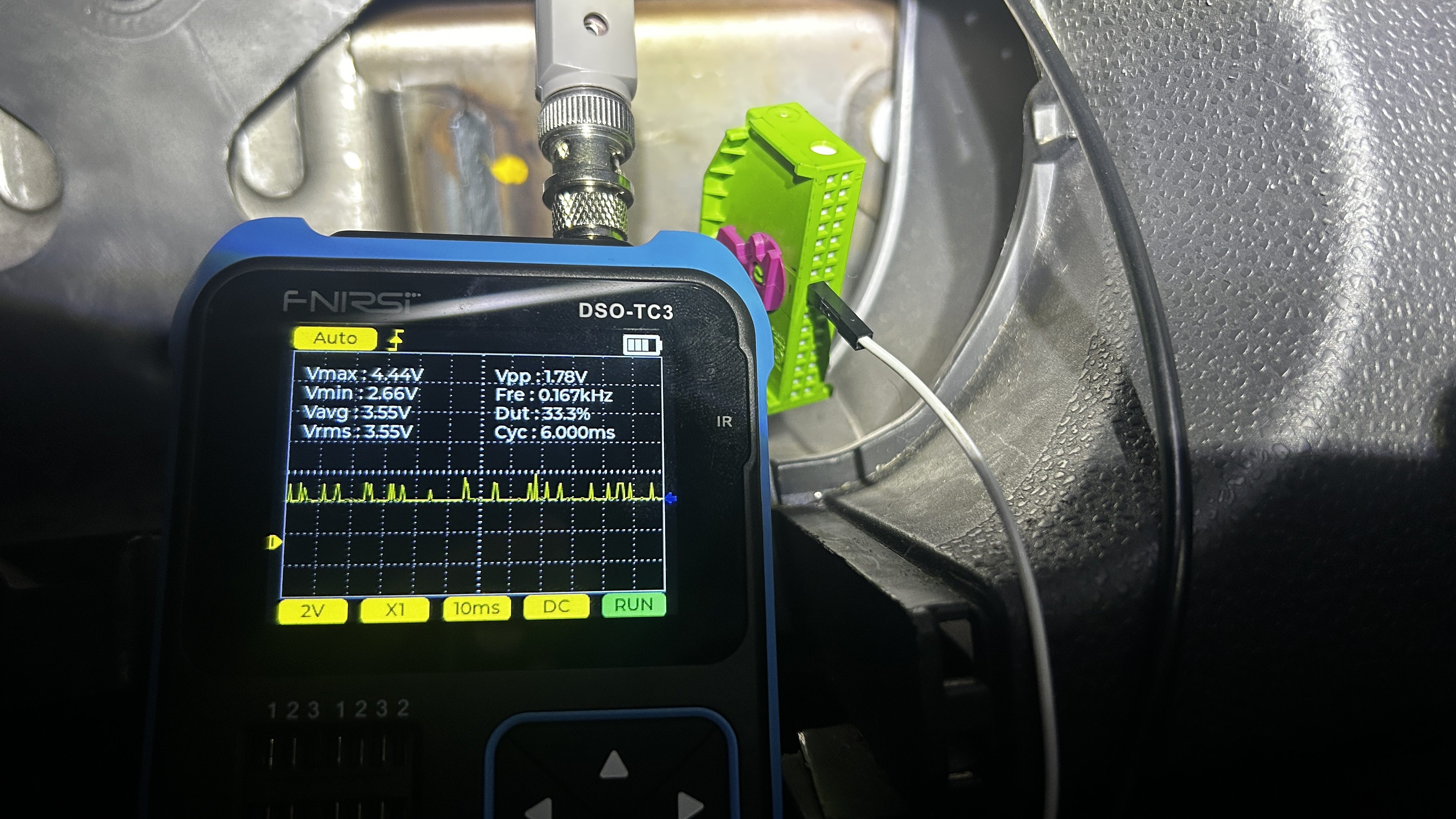
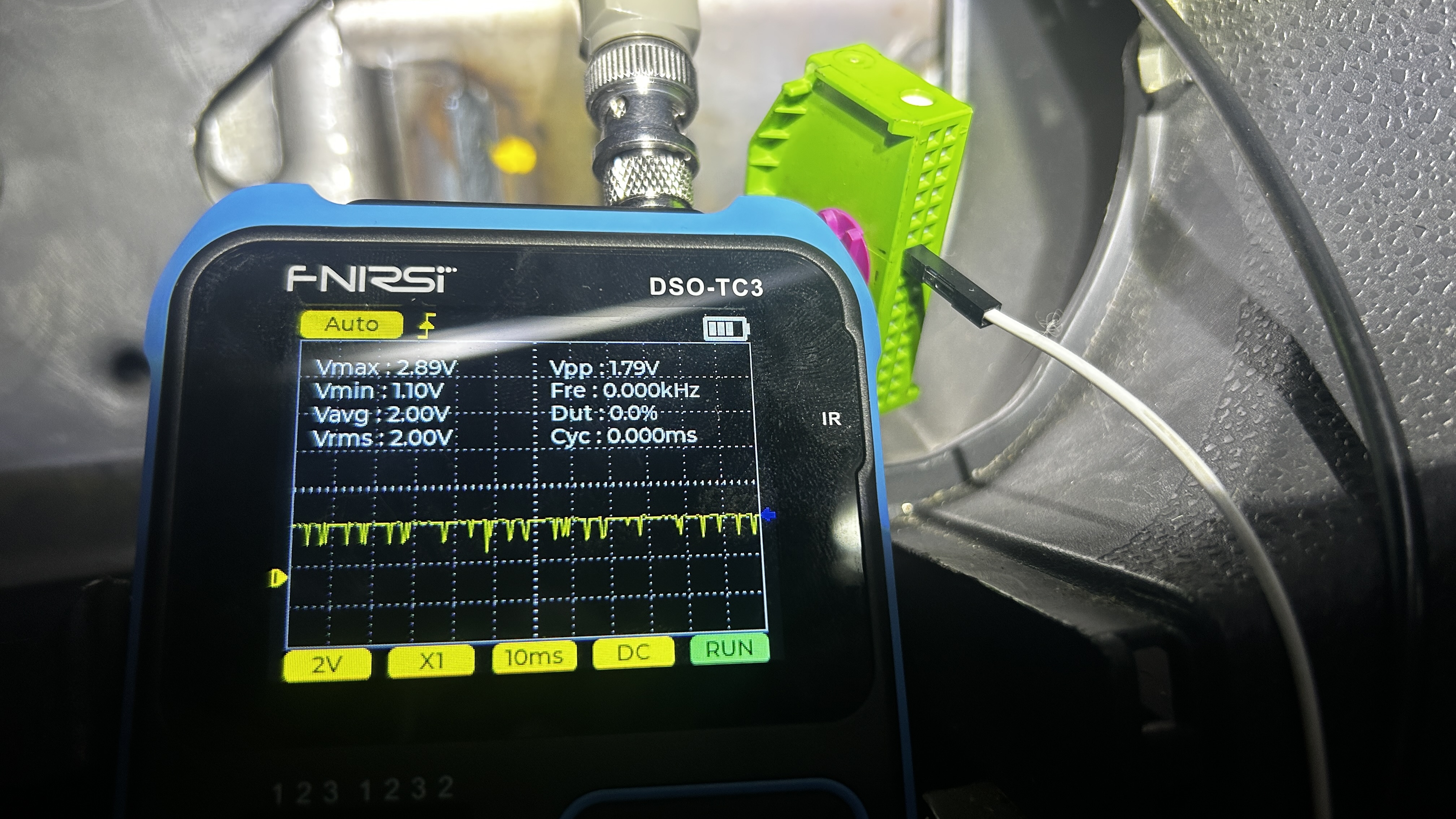
The connector housing was sealed, making it impossible to see which external pin corresponded to which wire. To avoid damaging the connector, I used an oscilloscope (which would be necessary later anyway) and probed each pin until I found the signals for CAN High and CAN Low.
Setting Up the CAN Sniffer Environment
After identifying the vehicle’s CAN bus, it’s time to configure our Arduino and MCP2515 to connect to it.
- Prepare the Arduino: Connect your Arduino Uno to your computer, open the Arduino IDE, and import the
arduino-mcp2515library you downloaded from this repository. - Upload the Firmware: Open the
slcan(Serial Line CAN) sketch available in my repository here:slcan.ino, and upload it to your Arduino. - Connect the Hardware: Wire the Arduino to the MCP2515 module according to the schematic below.
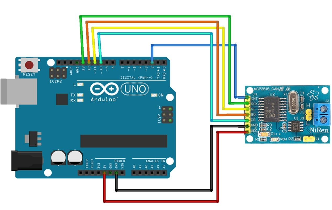
Your hardware is now ready to read and write data on the car’s CAN bus!
Pro-Tip: To test if your Arduino-MCP2515 setup is reading data correctly, open the Serial Monitor in the Arduino IDE and set the baud rate to 115200. If you see data being logged, congratulations! It’s working.
Sniffing the CAN Bus
From this point on, we will use the Python scripts from the can-utils-macos repository to interact with the CAN bus.
First, set up your Python virtual environment:
python3 -m venv venv
source venv/bin/activate
pip install --upgrade pip
pip install -r requirements.txt
Next, let’s use the cansniffer_interactive.py script to sniff CAN data.
# The device path /dev/cu.usbserial-A5069RR4 corresponds to my Arduino Uno.
# *Important:* This path will likely be different on your machine.
python cansniffer_interactive.py /dev/cu.usbserial-A5069RR4
With the sniffer running, the hard part begins: interacting with vehicle functions (pressing buttons, opening doors, etc.) and observing changes in the cansniffer output. After an intense search, I found something interesting related to CAN ID 470.
To get a cleaner view of just this ID, I used the candump.py tool, filtering for that specific ID.
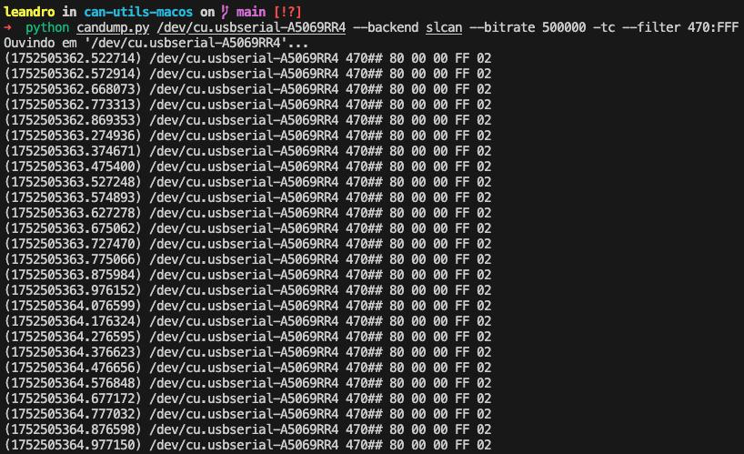
python candump.py /dev/cu.usbserial-A5069RR4 --backend slcan --bitrate 500000 -tc --filter 470:FFF
With the hazard lights OFF:
With the hazard lights ON:
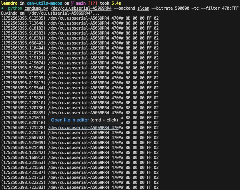
This allowed me to identify the following patterns (focusing on the first byte):
80 00 00 FF 02: Sent when the hazard lights are off.8B 00 00 FF 02and88 00 00 FF 02: Sent alternately when the hazard lights are on.
Now that we understand how the data works, we can inject our own.
Injecting Data
To control the hazard lights, we will use the cansend.py script to send our own CAN messages.
Message to turn the hazard lights ON:
python cansend.py /dev/cu.usbserial-A5069RR4 470#8B0000FF02
And it worked!
Message to turn the hazard lights OFF:
python cansend.py /dev/cu.usbserial-A5069RR4 470#800000FF02
Here is a video demonstrating the injection in practice:
Conclusion
Despite the challenges and the many hours spent exploring the vulnerabilities of my own car, it was incredibly rewarding to see this working on a real vehicle, not just in a lab or a CTF. I’m also pleased that I could complete this project with such a low-cost setup.
This project was heavily based on and inspired by the work of Faraday: How to unlock a door with a Doggie. Their content is amazing, so please check it out. I want to extend a special thanks to Gaston and Octavio from Faraday / Car Hacking Village, who helped me a great deal during these studies.
I hope this guide was helpful in some way. I will be presenting this research at conferences in Brazil, such as H2HC via the Car Hacking Village. Thank you for reading!
If you have any questions, feel free to reach out :)